In various engineering fields, be it architecture, mechanical, electrical, or others, engineering drawings are indispensable tools for communication and project execution. However, how to read engineering drawings can be challenging for many. In fact, once you decipher the meaning behind the lines, shapes, and symbols in these drawings, you can gradually grasp the information conveyed by the drawings accurately.
To aid you in this process, this article has compiled some common elements of engineering drawings and provided clear explanations for each. Save it for future reference, and it is believed that this information will help you quickly and precisely interpret the content of the drawings.
What are Engineering Drawings Used for
Engineering drawings play a pivotal role throughout the lifecycle of a project. They convey design intent. Made by hand or engineering design software, drawings take on different forms at different stages of the project, like conceptual drawings, bid drawings, and construction drawings. these drawings, in accordance with standards, outline all the information and requirements, accurately denoting the design proposals and overall structure for easy understanding and investment attraction.
Meanwhile, engineering drawings are the primary means of communication and exchange for various professional teams. This gives an incentive for seamless coordination when the project advances. Also, contractors and manufacturers rely on these drawings to execute specific operations. Upon completion, the engineering drawings will be a final verification basis. They guarantee that delivered products or projects meet the design specifications and overall quality.
Whether in design representation, communication methods, or verification documents, all these purposes are achieved based on the ability to read engineering drawings accurately. To guide you effectively, the following sections will briefly explain how to read engineering drawings from three aspects: information blocks, lines and views, as well as dimensions and scales.
Information Blocks
While information blocks may not be the most visually prominent elements, they contain the most information you can read in engineering drawings. These blocks provide precise information about the purpose of the drawing, the depicted objects, part numbers and descriptions, as well as details on materials and surface treatments. To read information blocks, you should figure out its three types in the following.
Title Block
Typically located in the bottom or right corner of the drawing, the title block is written within a table and includes the project name, designer, drawing status, and more. In essence, the purpose of the title block is to provide the basic background of the drawing, allowing the viewer to quickly grasp the intent and details. However, it is important to note that in case of any conflict between information in the external notes and that in the title block, the information in the external notes should take precedence and replace the title block information.

Revision Block
The revision block on an engineering drawing is typically positioned similarly to the title block, opposite to it. Its primary function is to provide detailed information about the changes made in the drawing. Generally, you can access revision descriptions, approval, and dates.
The revision block plays a significant role in the actual execution of a project. If you have any questions about the revision information, the details provided here can serve as a basis for inquiring about the reasons for modifications and approval. Moreover, in the case of contract disputes, the revision block is crucial evidence.

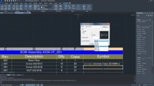
Bill of Materials Block
In engineering drawings, you can often find the bill of material block in the top left corner or above the title block. It includes detailed information such as part numbers, descriptions, quantities, and material specifications. This data is crucial for material management during procurement, manufacturing, and construction.
If you are using computer-aided design software like ZWCAD for drawing, the bill of material does not need to be manually filled in. Simple commands can automate all the data. Better yet, this CAD software for beginners can also automatically update material lists with drawing modifications.
Lines and Views
To learn how to read engineering drawings, a strong emphasis is also placed on understanding lines and views. The drawings you refer to are typically in plan view, lacking the three-dimensional visualization in CAD software. Therefore, different representations of lines and views play a critical role in providing a comprehensive portrayal of the engineering design.
Types of Lines
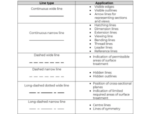
In engineering drawings, lines are basic expressions, taking on different styles and meanings based on factors like drawing position, contour thickness, and perspective. Here are several common types of lines to enhance your understanding of engineering drawings.
- Continuous wide line: Used for surfaces visible in the front view, indicating the contours and edges of the objects;
- Continuous narrow line: Used for representing imaginary intersection lines, projection lines, hatching lines, dimension lines, extension lines, short centerlines, and more;
- Dashed wide Line: May also be thin, used to depict the edges and outlines of the invisible surfaces of an object;
- Long-dashed dotted wide line: Used to indicate the position of cross-sections or to represent limited surface treatment areas;
- Long-dashed dotted narrow line: Frequently paired with a center mark to denote a centerline. Also used to indicate symmetry or for axis lines in front of sections.
Types of Views
To offer viewers detailed insights, engineering drawings portray objects from various angles and directions, known as views. The commonly readable views are essentially as follows.
- Orthographic view: Orthographic views form the foundation of drawings, comprising three primary view sets: the front view, the top view, and the side view. These views are generated by planes perpendicular to each other, providing a comprehensive depiction of the object;
- Isometric View: A drawing technique that portrays an object with equal distances and proportions in the horizontal, vertical, and depth dimensions. This method is commonly used to showcase the external appearance and shape of the object, emphasizing its overall structure;
- Partial view: A partial view can show the specific area of an object. It employs arrows with letters to indicate the portion to be illustrated and the direction of projection, making it easier for viewers to grasp the structure and details;
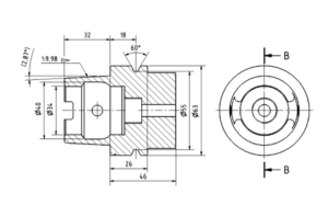
- Sectional View: By depicting a cross-section of an object, a sectional view is commonly is used to showcase the internal structure, material distribution, and critical features of an object. It provides important information for manufacturing, assembly, and maintenance;
Auxiliary View: An auxiliary view is used to show how a specific part of an object looks when projected onto a plane different from the main view. It’s handy for highlighting features that are inclined or oriented in directions other than the main view.

Dimensions and Scales
In addition to title blocks, lines, and views, grasping dimensions and proportions is essential for reading engineering drawings. Dimensions in engineering drawings typically provide quantitative information about the size, shape, and position of objects. To interpret dimensions correctly, locate a continuous narrow line drawn between two projection lines with an arrow on either end. The numbers adjacent to these lines represent the dimensions. If there are symbols next to the dimensions, they signify the following:
- Ø: Stands for diameter;
- H: Short for height;
- L: Short for length;
- ID & OD: Denotes inside diameter and outside diameter;
- Min & Max: Short for minimum and maximum.
Regarding scale, it’s essential to understand the relationship between two numerical values. Some scales, such as 1:1, 1:2, 1:5, or 1:10, where the first number represents the drawing size and the second number represents the actual size. To read the scale correctly, you need to locate the scale annotated at the bottom or side of the drawing and check for any scale-related annotations on the drawing. Then, combining these two, use a calculator to calculate the actual dimensions of the object. It’s important to pay attention to the units used in the drawing to ensure an accurate interpretation of the scale values.
Conclusion
Now that you know how to read engineering drawings, it is time to take a drawing and check if you’ve grasped the essentials of reading title blocks, lines, views, dimensions, and scale. Hope these reading tips will prove valuable to you. Yet, keep in mind that true proficiency in interpreting engineering drawings comes through daily practice.
Similar Posts:
- How Do You Enlarge Something In Illustrator?
- How To Draw On Photo Iphone?
- How To Draw On Photo Iphone?
- How To Draw With A Mouse: A Guide
- How To Draw On Instagram Photo?
- What Is The Job Of A Fashion Illustrator?
- What Is The Job Of A Fashion Illustrator?
- How Do I Delete Unnecessary Lines In Illustrator?
- How Do I Delete Unnecessary Lines In Illustrator?
- How To Draw On Instagram Photos?